GW Instek PSB-1400L - 400W Programmable Multi-Range DC Power Supply
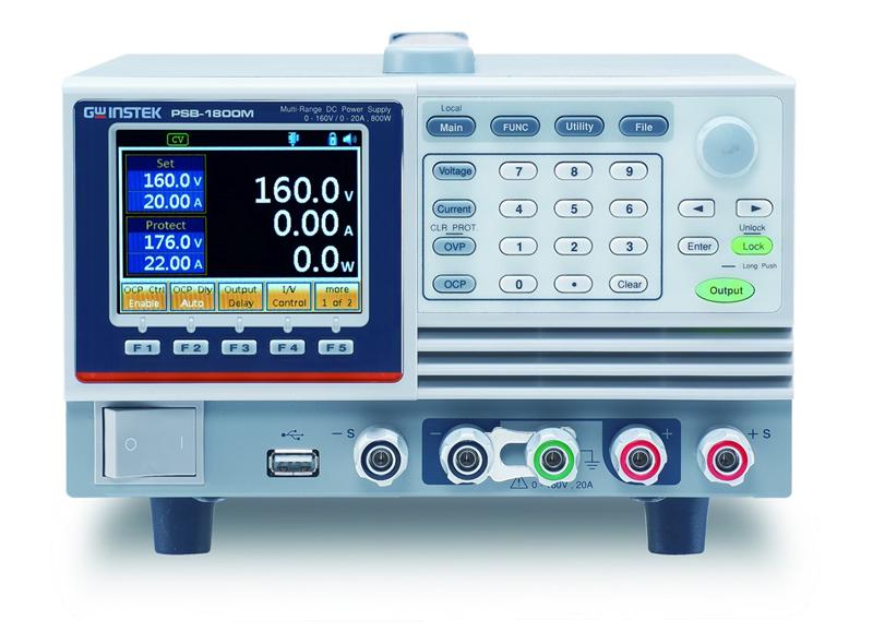

GW Instek debuts the PSB-1000 series, which is a single output channel, programmable and multi-range DC power supply. The series comprises 400W models: PSB-1400L(40V/40A); PSB-1400M(160V/10A), and 800W models: PSB-1800L(40V/80A); PSB-1800M(160V/20A). The maximum voltage output of 320V can be realized by placing 160V units in series connection. By connecting PSB-1800Lunits in parallel, the maximum current output of320Acan be achieved. The PSB-1000 series is a bench-top power supply featuring user friendly interface, which can clearly display setting conditions and measurement results via LCD display and menu-typed functionality selection without referring to the user manual. All settings can be done by functionality keys, numerical keys, and speed dial keys. The30Aoutput capability from the front terminal of the PSB-1000 series can better meet the requirements of laboratories and scientific R&D units.
The PSB-1000 series features user friendly menu-typed functionality interface and its built-in functionalities can better meet industry's application requirements. Both front panel and rear panel output terminals of the PSB-1000 series facilitate researchers to access power output conveniently. The display panel adopts menu-typed functionality selection to help users quickly familiarize with settings and operation that is extremely suitable for on-site engineers and R&D engineers who deal with complicated functional setting requirements. The Bleeder function helps rapidly bleed internal capacitors to avoid potential danger of discharging electric charge. For battery's charging applications, users can set Bleeder to Disable to avoid impact on battery charging applications. The I/V Control function, based upon DUT's requirements, sets rise and fall speed of voltage and current respectively to effectively reduce surge voltage and current output as well as to measure DUT characteristics. The CC priority output mode can be utilized to protect diode characteristic load and LED load from being damaged by inrush current. Sequence Function (SEQ), via editing Excel charts and uploading them to the instrument, automatically executes the required output waveforms to meet the requirements of related regulations and tests. The automatic execution of the sequence function is often applied to planning a set of continuous voltage variation to assess DUT characteristics. For instance, producing a series of voltage variation output to test impact on automotive fans is one of the reliability test applications. Power On Configuration allows users to select previously set SEQ to carry out automatic execution as soon as power is turned on. For production lines demanding sequential power supply output application requirements, tremendous time can be saved by this function, which exempts users from resetting sequential power supply when power is turned on every single time. Voltage Trigger allows users to set pulse signals for leading edge threshold and trailing edge threshold. VOLT TRIG can be applied to ATS by providing output time for working voltage via BNC adapter. The Output Delay function facilitates users to respectively set action time for power output on and power output off for multiple sets of PSB-1000 so as to realize sequential power output applications.
The PSB-1000 series is equipped with multi range power output capability providing fourfold rated power output to meet customers' flexible application requirements. The models and operating area of the entire series are as the following chart:
| Model name | Output Voltage | Output Current | Output Power |
| PSB-1400L | 40 | 40 | 400 |
| PSB-1400M | 160 | 10 | 400 |
| PSB-1800L | 40 | 80 | 800 |
| PSB-1800M | 160 | 20 | 800 |
Operating Area

Parallel/Series Operation
To augment output power so as to meet customers' large voltage and large current requirements, the PSB-1000 series, via placing two same model units in series connection, will be able to produce twofold rated voltage output, and through connecting four same model units in parallel, the PSB-1000 series can produce fourfold rated current output. The maximum voltage output of 320V can be achieved via placing the PSB-1000 series in series connection, and the maximum current of 320A and the maximum power of 3200W can be obtained through parallel connection.
| Parallel connection | 1 unit | 2 units | 3 units | 4 units |
| PSB-1400L | 40V | 40V | 40V | 40V |
| 40A | 80A | 120A | 160A | |
| PSB-1400M | 160V | 160V | 160V | 160V |
| 10A | 20A | 30A | 40A | |
| PSB-1800L | 40V | 40V | 40V | 40V |
| 80A | 160A | 240A | 320A | |
| PSB-1800M | 160V | 160V | 160V | 160V |
| 20A | 40A | 60A | 80A |
| Series Connection | 1 unit | 2 units |
| PSB-1400L | 40V | 80V |
| 40A | 40A | |
| PSB-1400M | 160V | 320V |
| 10A | 10A | |
| PSB-1800L | 40V | 80V |
| 80A | 80A | |
| PSB-1800M | 160V | 320V |
| 20A | 20A |
Power On Configuration
The PSB-1000 series provides different Power On Configurations for different users. Users can also set automatic execution procedures to be carried out as soon as power is turned on. After presetting Power On Configuration, each rebooting will have a short activation display to show present settings of Power On Configuration of the PSB-1000 series. The execution will be conducted by the power on mode.
Power On Configuration Parameters Include:
- CV control settings: Local(master), Ext-V(external voltage control), Ext-R↗, Ext-R↘(external resistance control)
- CC control settings: Local(master), Ext-V(external voltage control), Ext-R↗, Ext-R↘(external resistance control)
- PON automatic execution while power on: None (non execution), Output On (automatic output while power is on), SEQ0~SEQ9 (automatic sequence execution while power is on)
- Track series and parallel settings: Local (master operation), S/Slave (set as Slave under the series connection mode), P/Slave (set as Slave under the parallel connection mode), P2-P4/M (set as Master under the parallel connection mode)
- Ext-Out external analog output control:
- set High to indicate pin18-19 open circuit (Open) power output.
- set Low to indicate pin18-19 short circuit (Short) power output.
- Breaker:
- set Enable (while alarm is sounded, PSB-1000 will shut down automatically)
- set Disable (while alarm is sounded, PSB-1000 will cease outputting)
- Sense Control
- set Disable (non activation of internal Remote sense terminal)
- Set Rear (activation of rear panel internal Remote sense terminal)
- Set Front (activation of front panel internal Remote sense terminal)
 |
| POC Setting Screen |
Enable OCP Control
The On/Off of the OCP protection function can be selected from the master display screen and the OCP activation time can delay 0.1~2.0 seconds. This function can protect customers' DUTs from over current to avoid unexpected operations which lead to DUT damage caused by over current.

Voltage Trigger
Voltage Trigger allows users to set pulse signals for leading edge threshold Vt1 and trailing edge threshold Vt2. VOLT TRIG can be applied to provide output time for working voltage via BNC adapter. Users can determine positive or negative voltage trigger signals by Tref.

Voltage Trigger Setting

Vrig Triming Chart
Output Delay
Power output and on/off facilitate flexible planning and setting with respect to time.
- Set On Delays time to delay 0.00 ~ 100.00 seconds for power output
- Set Off Delays time to delay 0.00 ~ 100.00 seconds for power off

I/V Control
CV and CC priority can be set based upon customers' application requirements. The speed of voltage rise (V/s) or voltage fall (V/s), and the speed of current rise (A/s) or current fall (A/s) can be set respectively.
The PSB-1000 series provides customers with the following four modes to meet their requirements.
CCHS > current with maximum speed Slew Rate
CVLS > users set voltage Slew Rate
CCLS > users set current Slew Rate

Bleeder Circuit Control
The PSB-1000 series power supply has a bleeder circuit control which is in parallel with the output terminal. When power is off or load is disconnected, bleed resistor will consume electricity from the filter capacitor. Without a bleed resistor, the filter capacitor of power could still be charged with electricity that poses a potential danger. In addition, for ATE system, bleed resistor allows the PSB-1000 series to bleed current rapidly so as to prepare itself for the next operation.

Average Settings
Allow users to decide measurement average to be output based upon the requirements. Under Low level, the real time average can be displayed. On the contrary, under the High level, the higher average will be displayed.
Sequence Function
There are 10 sets of the Sequence function for customers to determine record settings. Automatically executing sequential waveforms can be done without the PC. For instance, sequential power output simulates the power supply of DUT's aging battery to understand the impact on DUT's characteristics.
Analog Programming Connector Function
On the rear panel of the PSB-1000 series, a 26-pin analog control terminal is designed to perform remote control and monitoring functions. External voltage or resistor can be utilized to set output voltage and current. The power supply output on/off control and master power shut-down can also be controlled by using the external switch. The analog control terminal is complied with the Mil 26-pin connector (OMRON XG4 IDC plug) standard.

This product has been discontinued.
- LCD display and menu-typed functionality selection
- Support front panel output terminals (Max.30A) and rear panel output terminals (Rating current output)
- Bleeder circuit control
- I/V Control function
- Sequence function
- Power on Configuration
- Internal Sense Control( Disable/ front panel/ rear panel)
- Voltage trigger function
- Output delay function
- OCP Control function
- Interface: USB Host, LAN, option: GPIB (PSB-105)
Output Rating
| Output Voltage(V) | 0~40 |
| Output Current(A) | 0~40 |
| Output Power(W) | 400W |
Regulation (CV)
| Load Regulation (mV) | 25 |
| Line Regulation (mV) | 23 |
Regulation (CC)
| Load Regulation (mA) | 45 |
| Line Regulation (mA) | 45 |
RIPPLE & NOISE (Noise Bandwidth 20MHz ; Ripple Bandwidth = 1MHz)
| CV p-p | 60 |
| CV rms | 7 |
| CC rms | 80 |
Programming Accuracy
| Voltage (0.1%+) | 10 |
| Current (0.1%+) | 20 |
Measurement Accuracy
| Voltage (0.1%+) | 10 |
| Current (0.1%+) | 20 |
Response Time
| Raise Time | 50 |
| Fall Time(Full Load) | 50 |
| Fall Time(No Load) | 500 |
| Load Transient Recover Time(Load change from 50 to 100%) | 1 |
Programming Resolution (By PC Remote Control Mode)
| Voltage | 1 |
| Current | 1 |
Measurement Resolution (By PC Remote Control Mode)
| Voltage | 1 |
| Current | 1 |
Series and Parallel Capability
| Parallel Operation | Up to 4 units including the master unit |
| Series Operation | Up to 2 units including the master unit |
Protection Function
| OVP | 4-44 |
| OCP | 4-44 |
| OHP | Turn the output off. |
Front Panel Display Accuracy, 4 Digits
| Voltage (0.1%+) | 20 |
| Current (0.1%+) | 20 |
Environment Condition
| Operation Temp | 0°C to 40°C |
| Storage Temp | -25°C to 70°C |
| Operating Humidity | 20% to 85% RH; No condensation |
| Storage Humidity | 90% RH or less; No condensation |
Other
| Analog Control | Yes |
| Interface | USB/LAN/GPIB(Option) |
| Power Source | 100Vac to 240Vac, 50Hz to 60Hz, single phase |
| Storage Humidity | 90% RH or less; No condensation |
| Dimensions | 214mm x 124mm x 350mm |
| Weight | Approx. 5.2kg |
Do you have a 400W Programmable Multi-Range DC Power Supply that needs to be calibrated?
We offer standard traceable calibration and ISO 17025 accredited calibration services.
Get your 400W Programmable Multi-Range DC Power Supply calibrated today! Click Here!
There are currently no reviews for this product.