Fluke 190-104 - Series III Scopemeter Test Tools


What's in the box:
- ScopeMeter Test Tool
- BC190/830 power adapter
- Power cord set
- BP291 Li-ion battery pack
- VPS410-II probe (4x)
- Hand strap
- Hanging strap
- USB-cable
- TRM50 cable terminator (4 pcs)
- CXT293 carrying case
- DWA-131 WiFi dongle
- FlukeView Activation instructions (paper)
- Printed instructions
*Included items vary based on model selected
High performance portable oscilloscopes engineered for harsh environments
Fluke 190 Series III ScopeMeter® Test Tools are engineered to go where you go, and tackle just about any troubleshooting job along the way. These CAT III 1000 V/CAT IV 600V rated test tools combine rugged portability with the high performance of bench oscilloscopes to help you take on the challenges of installing, commissioning and maintaining industrial machinery, automation and process controls, and power conversion electronics with ease—from DC to 500 MHz.
Choose from two or four channel models with a wide range of bandwidth options. Fast sampling rates up to 5.0 GS/s, 200 ps resolution and deep memory of 10,000 samples per channel allow high-accuracy capture and display of waveform details, noise, and other disturbances. Perform timing or amplitude related measurements on three phases or three-axis control systems, or simply compare and contrast multiple test points in a circuit under test. Features like TrendPlot™ Paperless Recorder, ScopeRecord™ Mode, Connect-and-View™ Triggering and a unique 100-screen Replay function help you quickly diagnose issues to minimize repair costs and downtime. These features make the oscilloscopes easy to use especially when diagnosing the most difficult problems like complex waveforms, induced noise, intermittent events and signal fluctuations or drift.
- Up to four independent floating isolated inputs, up to 1000 V
- Up to 5 GS/s real time sampling (depending on model and channels used)
- Deep memory: 10,000 points per trace waveform capture (scope mode)
- CAT III 1000 V/CAT IV 600 V safety rated instrument for industrial environments
- Up to seven hours of battery operation using BP291
- Large, bright color display is easy to view in nearly any environment
- Easy to store and view historical data and transfer to a PC via USB or Wifi
- Convenient battery access door for quick battery swaps in the field
- IP51 rating, dust and drip-proof
- Connect-and-View triggering for intelligent, automatic triggering on fast, slow and even complex signals
- Frequency spectrum using FFT-analysis
- Automatic capture and REPLAY of 100 screens
- ScopeRecord mode gives 30,000 points per input channel for low frequency signal analysis
- TrendPlot Paperless Recorder mode with deep memory for long- term automatic measurements
- 5,000 count DMM included in the 2-channel models

Measure from mV to kV safely
Independently isolated inputs allow you to make measurements in mixed circuits having different ground references reducing the risk of accidental short circuits. Conventional bench oscilloscopes without special differential probes and isolation transformers can only reference measurements to line power earth ground. ScopeMeter 190 Series III test tools are engineered to cover a wide application range from mV to kV, so you’re ready for anything from microelectronics to heavy-duty higher voltage electrical applications. 190 Series III 60MHz and 100MHz configurations include VPS421 100:1 probes for higher voltage applications, while the 200MHz and 500MHz configurations include VPS410-II 10:1 probes suitable for both microelectronics and higher voltage applications.
IP-51 rated for harsh environments
Rugged and shock-proof, ScopeMeter Test Tools are built for dirty, hazardous environments. With its sealed case, it can endure dust, drips, humidity and airborne pollutants. Every time you reach for ScopeMeter Test Tool you can be confident it will work reliably wherever your work takes you.
USB and Wi-Fi connectivity
The Fluke 190 Series III offers two USB ports, electrically isolated from measurement input circuits allowing you to quickly and easily transfer data to a PC, archive and share waveforms with OEMs, colleagues and support staff, or store waveforms, screen captures and instrument setups onto USB memory devices for later use. Easily transfer saved files via USB stick, direct connection via the USB interface or optional Wi-Fi connectivity. These files can be used for further data handling or in FlukeView-2 Software to study waveforms in greater detail.

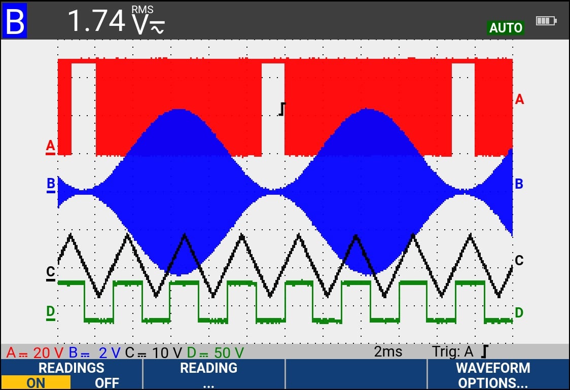
Connect-and-View triggering
Connect-and-View triggering provides an instant, stable display without the need for adjusting set- tings. If you’ve used other scopes, you know how tricky triggering can be. If settings are incorrect, results can be unstable or incorrect. Connect-and-View automatically sets up correct triggering by recognizing signal patterns. Without touching a button, you get a stable, reliable and repeatable display of virtually any signal including motor drive and control signals. It’s especially fast and convenient when you’re measuring a number of test points in rapid succession.

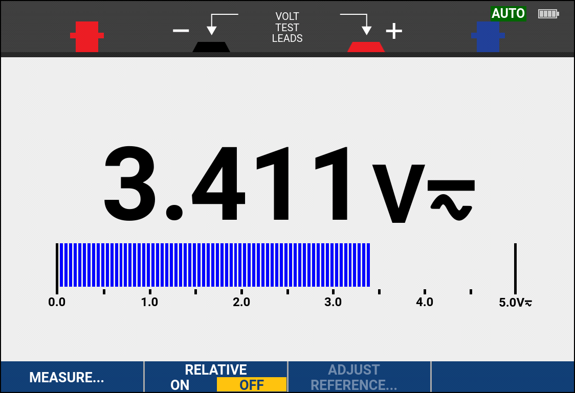
Built-in digital multimeter
Conveniently switch from waveform analysis to precise multimeter measurements using the built in 5000 count digital multimeter on two channel 190 Series III models. Measurement functions include Vdc, Vac, Vac+dc, resistance, continuity and diode test. Measure current and temperature using suitable shunt, probe or adapter with wide range of scaling factors.
What's in the box:
- ScopeMeter Test Tool
- BC190/830 power adapter
- Power cord set
- BP291 Li-ion battery pack
- VPS410-II probe (4x)
- Hand strap
- Hanging strap
- USB-cable
- TRM50 cable terminator (4 pcs)
- CXT293 carrying case
- DWA-131 WiFi dongle
- FlukeView Activation instructions (paper)
- Printed instructions
*Included items vary based on model selected
High performance portable oscilloscopes engineered for harsh environments
Fluke 190 Series III ScopeMeter® Test Tools are engineered to go where you go, and tackle just about any troubleshooting job along the way. These CAT III 1000 V/CAT IV 600V rated test tools combine rugged portability with the high performance of bench oscilloscopes to help you take on the challenges of installing, commissioning and maintaining industrial machinery, automation and process controls, and power conversion electronics with ease—from DC to 500 MHz.
Choose from two or four channel models with a wide range of bandwidth options. Fast sampling rates up to 5.0 GS/s, 200 ps resolution and deep memory of 10,000 samples per channel allow high-accuracy capture and display of waveform details, noise, and other disturbances. Perform timing or amplitude related measurements on three phases or three-axis control systems, or simply compare and contrast multiple test points in a circuit under test. Features like TrendPlot™ Paperless Recorder, ScopeRecord™ Mode, Connect-and-View™ Triggering and a unique 100-screen Replay function help you quickly diagnose issues to minimize repair costs and downtime. These features make the oscilloscopes easy to use especially when diagnosing the most difficult problems like complex waveforms, induced noise, intermittent events and signal fluctuations or drift.
- Up to four independent floating isolated inputs, up to 1000 V
- Up to 5 GS/s real time sampling (depending on model and channels used)
- Deep memory: 10,000 points per trace waveform capture (scope mode)
- CAT III 1000 V/CAT IV 600 V safety rated instrument for industrial environments
- Up to seven hours of battery operation using BP291
- Large, bright color display is easy to view in nearly any environment
- Easy to store and view historical data and transfer to a PC via USB or Wifi
- Convenient battery access door for quick battery swaps in the field
- IP51 rating, dust and drip-proof
- Connect-and-View triggering for intelligent, automatic triggering on fast, slow and even complex signals
- Frequency spectrum using FFT-analysis
- Automatic capture and REPLAY of 100 screens
- ScopeRecord mode gives 30,000 points per input channel for low frequency signal analysis
- TrendPlot Paperless Recorder mode with deep memory for long- term automatic measurements
- 5,000 count DMM included in the 2-channel models

Measure from mV to kV safely
Independently isolated inputs allow you to make measurements in mixed circuits having different ground references reducing the risk of accidental short circuits. Conventional bench oscilloscopes without special differential probes and isolation transformers can only reference measurements to line power earth ground. ScopeMeter 190 Series III test tools are engineered to cover a wide application range from mV to kV, so you’re ready for anything from microelectronics to heavy-duty higher voltage electrical applications. 190 Series III 60MHz and 100MHz configurations include VPS421 100:1 probes for higher voltage applications, while the 200MHz and 500MHz configurations include VPS410-II 10:1 probes suitable for both microelectronics and higher voltage applications.
IP-51 rated for harsh environments
Rugged and shock-proof, ScopeMeter Test Tools are built for dirty, hazardous environments. With its sealed case, it can endure dust, drips, humidity and airborne pollutants. Every time you reach for ScopeMeter Test Tool you can be confident it will work reliably wherever your work takes you.
USB and Wi-Fi connectivity
The Fluke 190 Series III offers two USB ports, electrically isolated from measurement input circuits allowing you to quickly and easily transfer data to a PC, archive and share waveforms with OEMs, colleagues and support staff, or store waveforms, screen captures and instrument setups onto USB memory devices for later use. Easily transfer saved files via USB stick, direct connection via the USB interface or optional Wi-Fi connectivity. These files can be used for further data handling or in FlukeView-2 Software to study waveforms in greater detail.
Connect-and-View triggering
Connect-and-View triggering provides an instant, stable display without the need for adjusting set- tings. If you’ve used other scopes, you know how tricky triggering can be. If settings are incorrect, results can be unstable or incorrect. Connect-and-View automatically sets up correct triggering by recognizing signal patterns. Without touching a button, you get a stable, reliable and repeatable display of virtually any signal including motor drive and control signals. It’s especially fast and convenient when you’re measuring a number of test points in rapid succession.
Built-in digital multimeter
Conveniently switch from waveform analysis to precise multimeter measurements using the built in 5000 count digital multimeter on two channel 190 Series III models. Measurement functions include Vdc, Vac, Vac+dc, resistance, continuity and diode test. Measure current and temperature using suitable shunt, probe or adapter with wide range of scaling factors.
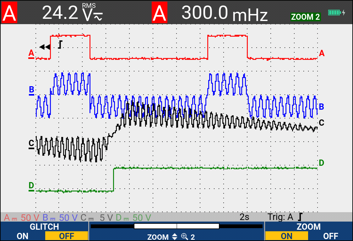
ScopeRecord™ mode for high resolution waveform recording
ScopeRecord memory stores up to 30,000 or more data points per channel, capturing fast intermittent events and glitches as short as 8 ns. (Two sets of multiple channel recordings can be stored to internal memory for later analysis.)
- Records events like UPS, power supply or motor start-up cycles
- With the Stop on Trigger mode, the ScopeMeter Test Tool automatically recognizes a power failure and stores the waveform data preceding it
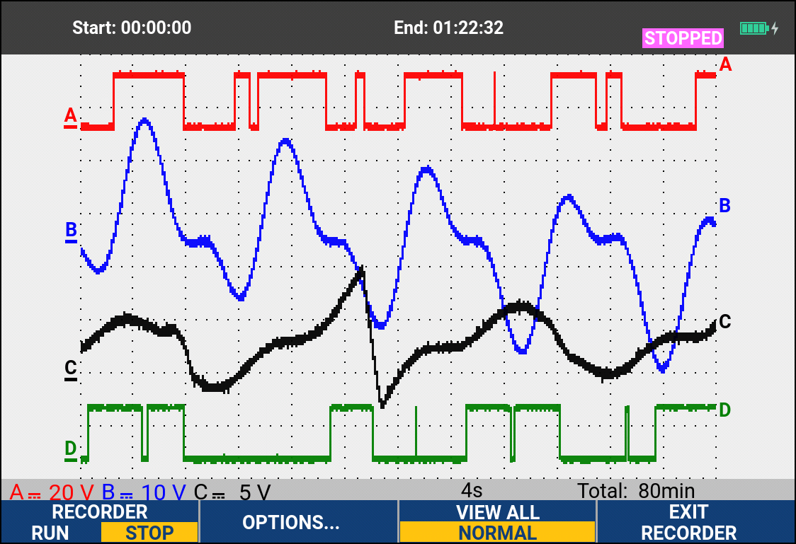
TrendPlot paperless recorder— records up to 11 days to help you find intermittent faults
The toughest faults to find are those that happen only once in a while. These intermittent events can be caused by bad connections, dust, dirt, corrosion, or simply broken wiring or connectors. Line outages, dips, swells and interruptions, or the starting and stopping of a motor can also cause a machine to stop. You may not be around when it happens, but the Fluke 190 Series III ScopeMeter Test Tool will be.
- Plot minimum and maximum peak values and average over time
- Plot any combination of up to four readings including voltages, amps, temperature, frequency and phase for all inputs, all with time and date stamp to pinpoint faults

FlukeView™ 2 ScopeMeter software for documenting, archiving and analysis
Get more out of your ScopeMeter Test Tool with FlukeView 2 ScopeMeter Software for Windows.
- Documentation—transfer waveforms, screens and data to your PC for printing or importing data into a report
- Add text to ScopeMeter Test Tool settings—give operators guidance when recalling settings
- Archive—create a library of waveforms for easy reference, or waveform comparison
- Analysis—use cursors or export data to another analysis program
- Rated for industrial environments CAT III 1000 V/CAT IV 600 V
- Automatically capture, view and analyze complex waveforms
- Large, bright color display for easy in-the-field viewing
- USB and Wi-Fi download for analyzing data with FlukeView® software
- Up to four independent floating isolated inputs, up to 1000 V
Oscilloscope Modes
| Vertical Deflection |
| ||||||||||||||||||||||||||
| Horizontal |
| ||||||||||||||||||||||||||
| Display and acquisition |
| ||||||||||||||||||||||||||
| Trigger and Delay |
| ||||||||||||||||||||||||||
| Automatic Capture of 100 Screens |
| ||||||||||||||||||||||||||
| FFT - Frequency Spectrum Analysis |
| ||||||||||||||||||||||||||
| Waveform Compare and Pass/Fail Testing |
| ||||||||||||||||||||||||||
| Automatic Scope Measurements |
| ||||||||||||||||||||||||||
| Cursor Measurements |
|
Meter Modes
| General |
The specified accuracy is valid over the temperature range 18 °C to 28 °C Add 10 % of specified accuracy for each degree C below 18 °C or above 28 °C | ||||||||||||||||||
| Voltage |
| ||||||||||||||||||
| Other Meter Functions |
| ||||||||||||||||||
Recorder Mode
| ScopeRecord RollMode |
| ||||||||||||||||||||
| ScopeRecord Roll Mode Sample Rate and Recording Timespan |
| ||||||||||||||||||||
| Trendplot Recording |
| ||||||||||||||||||||
| Cursor Measurements - All Recorder Modes |
|
General Specification
| Input Voltage Range |
| ||||||||||||||||||
| Memory Save and Recall |
| ||||||||||||||||||
| Case |
| ||||||||||||||||||
| Mechanical Data |
| ||||||||||||||||||
| Power |
| ||||||||||||||||||
| Safety |
| ||||||||||||||||||
| Environmental |
| ||||||||||||||||||
| Included Accessories |
|
Do you have a Series III Scopemeter Test Tools that needs to be calibrated?
We offer standard traceable calibration and ISO 17025 accredited calibration services.
Get your Series III Scopemeter Test Tools calibrated today! Click Here!
There are currently no reviews for this product.
Recommended Accessories for the Series III Scopemeter Test Tools
![]()
Rugged Protective Carrying Case, IP67 rated
![]()
ScopeMeter Compact Probe
![]()
Coaxial Feed-through Male to Female Cable Terminator